Brea Electric is the oldest business in Brea.

Understanding the Colors of Electrical Wires

Understanding the Colors of Electrical Wires: Guide to Electrical Safety

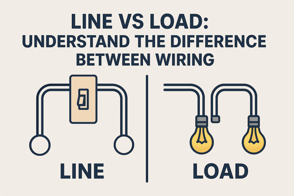
Electricity powers nearly every aspect of our lives—from the lights in our homes to the appliances we depend on daily. Yet, behind the walls, under the floors, and in the ceilings, a complex system of electrical wires ensures everything runs smoothly. One of the most crucial elements in this system is color coding. If you’ve ever opened an outlet box or seen a group of wires, you might have noticed that they’re not all the same color. These colors are not chosen at random—they serve a vital role in identifying the function and safety of each wire. At Brea Electric, our licensed electricians stress the importance of understanding these wire colors before attempting any electrical work. In this blog, we’ll break down the color codes for electrical wires, their meanings, and why it’s essential to understand them—even if you’re not an electrician. Why Wire Color Coding Matters Color coding in electrical wiring isn’t just a convenience—it’s a safety standard. These codes are regulated by the National Electrical Code (NEC) in the United States to help electricians and homeowners: Mishandling the wrong wire can result in serious injuries, property damage, or even fatal electrocution. That’s why understanding wire colors is one of the most important safety basics in any electrical project. Common Electrical Wire Colors and Their Meanings Let’s explore the most commonly used wire colors in residential and commercial wiring systems across the U.S., what each represents, and where you’re likely to encounter them. 1. Black Wires — The Standard Hot Wire Meaning: Hot or LiveFunction: Carries electrical current from the power source to outlets or fixturesUsed In: Switch legs, outlets, lights, appliances Black wires are perhaps the most universally recognized in electrical systems. These are live wires that carry electricity from the service panel to the device in use. When dealing with black wires, always assume they are energized, even when switches are off. Safety Tip: Never attempt to touch or modify a black wire unless the power is completely turned off at the breaker panel. 2. Red Wires — Secondary Hot Wire Meaning: Secondary HotFunction: Used for interconnection between smoke detectors, or in 220-volt setupsUsed In: Three-way switches, hardwired smoke detectors, split-phase systems Red wires are also hot wires, often used in switch legs or to link hardwired smoke detectors so that if one alarm goes off, all do. They’re commonly seen in setups requiring multiple hot wires, like 240V outlets or three-way switch configurations. 3. White Wires — Neutral Meaning: NeutralFunction: Carries electricity back to the breaker panelUsed In: Almost all residential and commercial circuits While white wires are neutral, they still carry current—just in the opposite direction. After the electricity flows through a device, it returns through the white neutral wire to the electrical panel, completing the circuit. Important Note: In some rare cases, a white wire may be tagged with black or red electrical tape to indicate it’s being used as a hot wire—especially in switch loops. Always double-check. 4. Green Wires — Ground Meaning: GroundFunction: Provides a path for electrical current to reduce the risk of electrocutionUsed In: All grounded electrical systems Green wires are essential for electrical safety. They connect your devices and appliances to the earth, ensuring that stray currents safely dissipate in the event of a short circuit. They are never used for live current. 5. Bare Copper Wires — Ground (Alternative) In many homes, especially older ones, you’ll find bare copper wires serving the same function as green ones. These uninsulated wires are typically ground wires and serve the same safety purpose. 6. Blue and Yellow Wires — Travelers and Switch Legs Blue WiresMeaning: Traveler wire or hot wireFunction: Used in three- or four-way switch configurationsUsed In: Complex switch setups, lighting controls Yellow WiresMeaning: Switch legFunction: Transfers power to a light or fanUsed In: Switch loops, ceiling fans, structural wiring While not as common in everyday wiring, blue and yellow wires are used for more complex control systems. If your home has multiple switches controlling a single light fixture, these are the colors you’re likely to see. Color Coding in 240V and Three-Phase Circuits In residential applications, most wiring is for 120V single-phase, but in some cases—especially in garages, workshops, or commercial buildings—you’ll see 240V or three-phase wiring. Here are common color codes: Wire Type Color Hot (L1) Black Hot (L2) Red Hot (L3 – if used) Blue Neutral White Ground Green or Bare Copper When working with three-phase power, the color codes can vary slightly by region or specific use, so always consult a professional electrician like those at Brea Electric for proper guidance. Color Coding for Low Voltage Wiring (Thermostats, Doorbells, etc.) Low-voltage systems like doorbells, thermostats, security systems, and audio wiring may follow different conventions depending on the manufacturer or installer. These wires typically operate at less than 50 volts, but they should still be handled with care and proper understanding. Color Misconceptions & Regional Variations Although the NEC provides standards for wire colors in the U.S., some older homes or installations by non-certified individuals may not follow proper codes. If you’re uncertain about any wiring, it’s safest to consult a certified electrician from Brea Electric, serving California residents with professionalism and care for over 40 years. Line vs Load: Understand the diffrence between wiring – CLICK HERE Common Mistakes to Avoid When Working with Electrical Wiring When to Call a Licensed Electrician Working with electrical systems isn’t a typical DIY project. If you encounter any of the following, it’s time to call in a professional: The team at Brea Electric is always ready to help homeowners and businesses ensure that their electrical systems are safe, efficient, and up to code. Final Thoughts: Wire Colors Are More Than Just Visual Cues Understanding the colors of electrical wires can help you stay informed and safe—especially when dealing with basic home electrical inspections or upgrades. However, always remember that color codes are only part of the safety equation. The safest and most reliable way to handle any electrical

Understanding the Colors of Electrical Wires: Guide to Electrical Safety Read More »

How to Change Hard-Wired Smoke Detectors

How to Change Hard-Wired Smoke Detectors: A Step-by-Step Guide for Homeowners

Smoke detectors are one of the most important safety features in your home. While battery-operated models are easy to replace, hard-wired smoke detectors offer added reliability and are often required by building codes. If your system is more than 8–10 years old or begins to chirp even with new batteries, it’s time for a replacement. In this guide, we’ll walk you through how to change hard-wired smoke detectors safely and efficiently, even if you’re not a licensed electrician. Why Change a Hard-Wired Smoke Detector? Most people don’t realize that smoke detectors have a limited lifespan, usually around 10 years. Here are a few reasons why replacing yours is essential: Tools and Supplies You’ll Need Before you begin, gather these items: Step-by-Step: How to Replace a Hard-Wired Smoke Detector Step 1: Turn Off Power at the Breaker To avoid electric shock, turn off the power to the smoke detector circuit at your home’s breaker box. Use a non-contact voltage tester to double-check that no power is running to the unit. Step 2: Remove the Old Smoke Detector Pro Tip: Take a photo of the wiring setup before disconnecting for easy reference later. Step 3: Check and Match Wires Step 4: Install the New Mounting Bracket (If Needed) Many new smoke detectors come with a mounting plate. If the new detector doesn’t fit the old bracket: Step 5: Connect the New Smoke Detector Step 6: Attach the New Detector Step 7: Restore Power and Test When Should You Call a Professional Electrician? While many homeowners feel comfortable replacing hard-wired smoke detectors, certain situations require expert help: FAQs About Change Hard-Wired Smoke Detectors Conclusion: Stay Safe with Proper Maintenance Replacing your hard-wired smoke detectors isn’t just about compliance—it’s about keeping your family and property safe. Regular maintenance and timely replacements are key to ensuring your fire safety system works when you need it most. If you prefer professional help, trust licensed electricians to get the job done right the first time. Line vs Load: Understand the diffrence between wiring – CLICK HERE Need Professional Help in California? If you’re located in Orange County or nearby areas, the trusted experts at Brea Electric can help you install, replace, or upgrade your smoke detectors quickly and safely. With over 60 years of experience in electrical services, we ensure your home meets the highest safety standards. Contact Brea Electric today for a free consultation!

How to Change Hard-Wired Smoke Detectors: A Step-by-Step Guide for Homeowners Read More »

Line vs Load

Line vs Load: Understand the diffrence between wiring

Line vs Load: In the electrical trades, the words “line” and “load” are short for the electrical wires that bring electricity from the source to a device (line) and the wires that send power to other devices further down the circuit (load). Incoming vs. outgoing wires, as well as upstream vs. downstream, are some of the more conversational phrases used to describe the same thing. What Is a Line Wire? The two words are used in reference to a single device and electrical box. The lines that deliver power into the box are referred to as line wires, upstream wires, or incoming wires. What Is a Load Wire? The wires that connect to other devices are referred to as load, downstream, or outgoing wires. These phrases refer to the device’s location in the circuit, as the load wire from one outlet becomes the line wire for the next receptacle downstream in the circuit. The phrases “line” and “load” are used in a variety of contexts across an electrical system. What’s the Difference Between Line vs Load Wiring? An electric meter’s line side receives the utility company’s incoming feed. It feeds the line side of an electrical service panel or disconnect after exiting the meter from the load side. Line and load connections are also included on the service panel; the line supplies power to the main breaker, and the individual branch circuit breakers may be regarded as the load in relation to the main breaker. How the Line and the Load Wire Can Be Distinguished Position of the WireBecause they are supplying power, line wires are typically located lower than load cables. Typically, load cables are placed close to the top of switches and outlets. Wire Color: Typically, load wires are white, and line wires are black. This isn’t always the case, though. Think about more than just color when determining which wire is which. Examining the WireTo determine which wire is which, you can also use a multimeter and a non-contact voltage tester, among other tools. Think about one of these choices as well if you’re not happy with your results when you’re just looking at position and color. When is it necessary to distinguish between a line wire and a load wire? CircuitsOn a single circuit, outlets (receptacles), switches, light fixtures, and other electrical devices are usually connected in multiples. The wire that connects the first device to the service panel is called the line, and the wire that connects the first device to the second device downstream on the circuit is called the load. The wire leading to the third device on the circuit is the load, the line is the power source entering from the first device at the second device, and so on. The device itself can have the same meaning. The incoming source power is connected to the line side of an outlet. Power exits the device (or electrical box) and moves down the circuit on the load side. Outlets for GFCIWhen connecting ground-fault circuit-interrupter (GFCI) outlets, line and load have a specific significance. The screw terminals on GFCIs are labeled LINE and LOAD, respectively, and are used to connect wires. When the line terminals are connected, the outlet only offers GFCI protection for that outlet. That outlet and other standard outlets downstream on the same circuit are protected by GFCI when the line and load terminals are connected (using two electrical cables or two sets of pigtail wires). Different Interpretations of Line vs Load To differentiate the components of the circuit that are at full household voltage (typically 120 volts) from the low-voltage wiring and devices that are used after the voltage is stepped down at a transformer, the term “line” is used when wiring low-voltage circuits, such as those that supply doorbells or landscape lights. The electrical demand, or power draw, that an appliance or gadget places on a circuit is also referred to as “load” in general. To get the “total load,” or maximum possible power consumption of all the lights on a lighting circuit, for instance, you can add up the maximum wattage of each light fixture on the circuit. Get more info about breaelectric – CLICK HERE

Line vs Load: Understand the diffrence between wiring Read More »

Accessibility Toolbar